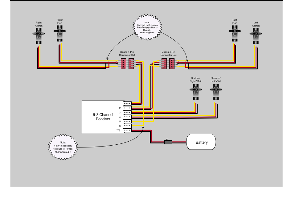
Full-House Sailplane Wiring Diagram
A simplified diagram illustrating how to utilize a 4-Pin Deans-style connector and a 6-8 channel receiver for connecting two servos in
each wing of a sailplane with separate ailerons and flaps. And this diagram allows you to hookup two additional
servos for a v-tail configuration.

Attach the Deans 4-Pin connector at the root of where the wings attach to
fuselage. This way when you put the wings on, your connections to the servos
will be all setup and ready-to-fly!
Note, if you can't find those pesky 4-pin Deans connectors, you can substitute multiplex (MPX) connectors as well.
Note, if you can't find those pesky 4-pin Deans connectors, you can substitute multiplex (MPX) connectors as well.
